


Traction Passenger Elevator functions
- Energy-saving and efficient: The traction system provides smooth and efficient operation through the cooperation of wire rope and motor, and has lower energy consumption than hydraulic elevators.
- Smooth and comfortable: The use of advanced traction technology and control system ensures that the elevator is stable and comfortable during acceleration and deceleration.
- Low maintenance cost: The equipment is durable, has a low failure rate, is easy to maintain, and reduces operating costs.
- Applicable to high-rise buildings: Especially suitable for high-rise buildings, with heavy loads and fast speeds, meeting large traffic needs.
- Intelligent control: Equipped with advanced intelligent control systems, it supports precise scheduling management and improves the user experience.

Elevator parts
Volkspace pays attention to details and achieves quality.


FAQ
What are the advantages of Traction Passenger Elevator?
Compared with hydraulic elevators, traction elevators are suitable for higher floors, with high operating efficiency and low maintenance costs.
How many floors are suitable for traction elevators?
Generally speaking, traction elevators are suitable for high-rise buildings with more than 10 floors, but with technological advances, existing designs can support higher floors.
How is the speed of traction elevators controlled?
The speed of the elevator is controlled by the motor and the speed regulating device to ensure smooth movement of passengers between different floors.
How is the safety of traction elevators guaranteed?
Traction elevators are equipped with multiple safety devices, including emergency braking system, overload alarm and redundant power supply to ensure safety.
One of our Brazilian clients was very concerned about the stability and comfort of the elevators when purchasing them from us. So our engineers conducted vibration simulations and tests, which solved the client's problem. We found that many other people have the same concerns, so please read on to see if we can address your concerns.
A Brazilian client purchased a traction elevator from us. The elevator has a load capacity of 2000 kg, a speed of 2.5 m/s (reaching a maximum of 4 m/s during some testing phases), and a lifting height of 100 m. Through detailed modeling and experimental simulation analysis of the elevator's relevant vibration components, we obtained relevant test data. This data provides theoretical support and practical application value for the comfort design of high-speed elevators.
3D model of car frame components
The elevator car frame mainly consists of upper beams, lower beams, and vertical beams. A shock-absorbing pad assembly buffers vibrations at the car bottom connection. The upper and lower beams are primarily welded from channel steel.
The upper beam uses 25[a] type channel steel, and the vertical beams are bent from 6mm Q235 profile. The lower beam is 20[b] channel steel. The car top and bottom are also components of the car frame, each composed of several plates spliced together, with additional reinforcing ribs forming a plate-like structure. These are connected to the upper and lower beams of the car frame via shock-absorbing components.
The car frame is primarily the load-bearing part of the elevator. During operation, it carries the car and connects to the traction machine and counterweight. Therefore, the quality of the car frame design largely determines the comfort of the car.


Elevator horizontal vibration is a crucial factor affecting human comfort. People are generally sensitive to vibration frequencies between 1 and 25 Hz, with the highest sensitivity occurring between 0.1 and 2 Hz horizontally and 4 and 8 Hz vertically. Therefore, it is essential to avoid these vibration frequencies during elevator design. This is achieved by analyzing the natural frequencies of elevator components to prevent resonance between them.
Dynamic analysis is a technique used to determine the dynamic behavior when inertia and damping play a significant role. Typical dynamic behaviors include structural vibration characteristics, such as the structure's vibration and natural frequencies, the effects of loads changing over time, and alternating load excitation. Dynamic analysis can simulate physical phenomena including vibration shocks, alternating loads, seismic loads, and random loads.
The equilibrium equations followed by the dynamic analysis are:

[M]--Mass matrix;
[C]--Damping matrix;
[K]--Stiffness matrix;
[x]--Displacement vector;
x']--Velocity vector;
x"]--Acceleration vector;
{F(t)}--Force vector;
Dynamic analysis is applicable to conditions involving rapid loading and impact collisions. In such cases, the effects of impact force and damping cannot be ignored. If the structure is statically determinate and the load velocity is relatively slow, the dynamic calculation results will be equivalent to the static calculation results.
Because dynamic problems must consider the inertia of the structure, material parameters must be defined for dynamic analysis, including material density. Additionally, the elastic modulus and Poisson's ratio are also essential input parameters.
Modal analysis of elevator system
To improve modeling accuracy and simplicity, the model was simplified by removing various chamfers and holes in the beam, and ignoring some unimportant components. Material properties, constraints, and loads were then set. Our engineers performed modal analysis. During the analysis, property settings such as frequency and solver type were required. The calculated resonant frequency was sufficient. Dynamic response analysis is performed after modal analysis, so mass-related factors are crucial to the calculation model.
Modal analysis simulation calculation
Theoretically, an infinite number of mode shapes can be obtained. For the sake of simulation simplicity, only the first six are considered. The frequency diagram of the sixth vibration order calculated by modal analysis is shown in the figure.As shown in the figure, under no-load conditions, the natural frequencies of the first six mode shapes are 0, 2.5, 5.0, 8.7, 16.8, and 25.9 Hz, respectively. Considering the half-load and full-load conditions, as well as the variation of the car frame at different heights, it is parametrically processed, and the natural frequency variations of the car frame under no-load, half-load, full-load, and bottom, middle, and top load conditions are listed.


|
Operating conditions |
Load conditions |
First order | Second order | Third order | Fourth level | Fifth Order | Sixth Order |
|---|---|---|---|---|---|---|---|
| Bottom layer | Unloaded | 0.01 | 2.47 | 5.05 | 8.72 | 16.84 | 25.95 |
| Bottom layer | Half-loaded | 0.01 | 2.47 | 5.02 | 8.66 | 16.79 | 25.34 |
| Bottom layer | Full-loaded | 0.01 | 2.42 | 4.98 | 8.54 | 16.53 | 25.12 |
| Middle layer | Unloaded | 0.02 | 2.49 | 5.07 | 8.73 | 16.89 | 26.01 |
| Middle layer | Half-loaded | 0.01 | 2.47 | 5.04 | 8.71 | 16.77 | 25.97 |
| Middle layer | Full-loaded | 0.01 | 2.44 | 5.01 | 8.69 | 16.01 | 25.66 |
| Top layer | Unloaded | 0.02 | 2.52 | 5.11 | 8.92 | 17.04 | 26.33 |
| Top layer | Half-loaded | 0.01 | 2.51 | 5.08 | 8.76 | 16.93 | 26.01 |
| Top layer | Full-loaded | 0.01 | 2.45 | 4.92 | 8.34 | 16.23 | 25.74 |
Modal analysis results analysis
1. The natural frequency of the car frame system is not constant; its value varies with different preloads and positions.
2. As shown in the table, the natural frequency decreases with increasing load. Therefore, the weight of the car frame (i.e., increasing the weight of the car itself or the interior decoration) can be appropriately increased to reduce the impact of vibration frequency on the human body.
3. Under the same load, the natural frequency tends to increase with increasing height, with higher orders showing greater variation. Therefore, measures should be taken to mitigate the influence of acceleration, keeping the velocity curve within a reasonable range.
We conducted modal vibration simulations under various operating conditions, obtained the simulation results, analyzed the relationships between different results, and identified the frequency distribution, thus preventing resonance with other components. This provides valuable theoretical support for the vibration reduction design of elevators.
Of course, in practical designs, rubber vibration damping components can be appropriately added to buffer resonance caused by stiffness connections between components. Alternatively, improving the structure of the vertical beam by adding a buffer component in the middle of the beam can also achieve a vibration reduction effect.
Vertical vibration model of elevator system
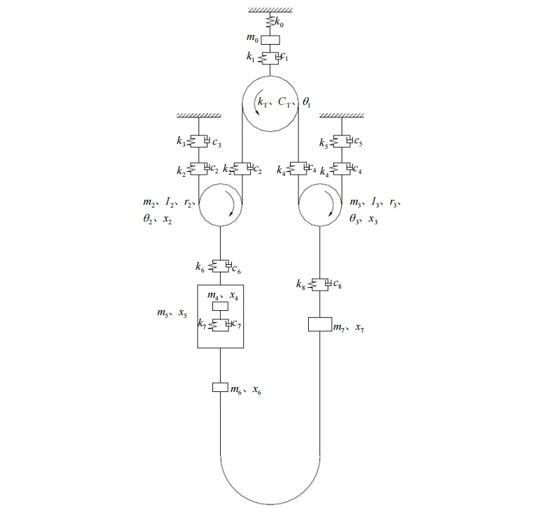
Traction passenger elevators are the most widely used type of elevator in the world today. This type of elevator has advantages such as high safety and reliability, high lifting height, and compact structure[59]. The vertical dynamic model of this type of elevator system consists of the traction machine spacer beam, traction machine damping rubber, traction sheave (equivalent traction sheave) wire rope system, car frame and car frame damping pad, compensation chain, rope head spring, etc. In the actual modeling process, it can be further simplified. When modeling, it is necessary to consider whether the elevator has a compensation chain device and tensioning system, which will affect the accuracy of the system. In addition, if the stiffness of the compensation chain is not considered, its mass characteristics should also be considered.
Dynamic analysis is a technique used to determine the dynamic behavior when inertia and damping play an important role. Typical dynamic behaviors include the vibration characteristics of the structure, such as the vibration and natural frequency of the structure, the effect of load changing with time, or alternating load excitation. The physical phenomena that dynamic analysis can simulate include: vibration impact, alternating load, seismic load, random load, etc.
| Serial Number | Parameter name | Value (maximum 4) | unit |
|---|---|---|---|
| 1 | Traction machine power | 28.2 | KW |
| 2 | Inverter power | 37 | KW |
| 3 | Traction wheel diameter | 500 | mm |
| 4 | Car height | 2600 | mm |
| 5 | Car weight | 1800 | Kg |
| 6 | Rated load | 2000 | Kg |
| 7 | elevator rated speed | 2.5 | m/s |
| 8 | traction ratio | 2:1 | - |
| 9 | Number of traction ropes | 6 | root |
| 10 | Traction rope diameter | 10 | mm |
| 11 | Lifting height |
100
|
m
|
| 12 | One-way transport time |
40
|
s
|
| 13 | Structural beam length |
3000
|
mm
|
| 14 | Guide rail support distance |
2000
|
mm |
| 15 | Hydraulic shaft width |
3200
|
mm |
| 16 | Hydraulic shaft depth |
2800
|
mm |
| 17 | Top floor height |
5600
|
mm |
| 18 | Pit depth |
3300
|
mm |


Our Results
1. Static analysis was conducted on the main components of the elevator. First, the structural strength of the safety components was checked, primarily through stress analysis of the elevator car frame. Stress, strain, and total deformation analysis contour maps of the main components of the car frame (upper beam, vertical beam, and lower beam) were obtained. The analysis showed that the strength fully meets safety standards.
2. Modal analysis was performed on the entire elevator car frame, obtaining the natural frequencies and vibration images of the elevator car frame under various operating conditions. The sixth-order vibration of the elevator and its vibration laws were analyzed, revealing the influence of parameters on elevator vibration. The frequency distribution was identified, thus preventing resonance with other components and providing valuable theoretical support for elevator vibration reduction design.
3. A 9-DOF vertical vibration simulation model of a 2:1 traction elevator was established. MATLAB engineering software was used to solve for the variation of the natural frequencies of each system with load Q and lifting height H. Based on the data, the influence of certain components on the natural frequencies of the elevator system was analyzed: under different stiffness variations of the damping pads, the natural frequency of the system increases with increasing stiffness; the elevator load Q has a relatively small impact on stiffness changes, but the car position is more sensitive and varies significantly; the natural frequency of the elevator system increases with increasing spring stiffness, but the increase slows down after the stiffness reaches a certain value.
4. The prototype was tested and verified. Using a PMT vibration instrument, various elevator operation conditions were tested, simulation data were compared, and improvement measures were proposed. The replaced elevator prototype was tested: the maximum vibration frequency during upward movement decreased from 44.6 Hz under full load to 18.7 Hz, while the maximum vibration frequency during downward movement decreased from 67 Hz under full load to 34.6 Hz, which fully achieved a relatively ideal vibration effect.
Hot Tags: traction passenger elevator, China traction passenger elevator manufacturers, suppliers, factory, elevator for shopping centers, elevator for making buildings more smooth running, elevator for complying with safety standards, elevator ventilation for passengers, elevator for making buildings more efficient, elevator for lifting passengers
