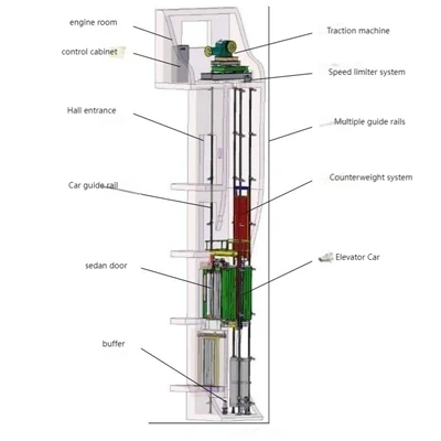
Traditional machine-room-less passenger elevators mostly adopt a counterweight side-mounted structure. Due to the limitations of the hoistway, the elevator cars are mostly deep and cannot offer the same spacious feel and good visibility as elevators with machine rooms and wider cars. Based on this, Volkspace has designed a bottom-supported, machine-room-less passenger elevator with a rear-mounted counterweight, utilizing a new arrangement of the hoistway top support beam, top deflection pulley, and car deflection pulley.

Why Choose Volkspace MRL Elevator
-
No Machine Room Needed
Compact design that saves construction cost and space, making it ideal for both new and existing buildings. -
Energy Saving & Eco-Friendly
Uses a gearless traction system that consumes up to 30% less power compared to conventional elevators. -
Smooth & Silent Operation
Advanced drive control system ensures stable movement, low noise, and minimal vibration - delivering a premium passenger experience. -
Elegant Design & Custom Finishes
Choose from glass, stainless steel, or mirror interiors to match your architectural style. -
High Safety Standards
Equipped with multi-level protection systems and certified under ISO9001, CE, EN81, and EAC standards. -
Easy Installation & Maintenance
Modular structure and pre-assembled components simplify the installation process and reduce downtime
Customization Options
Cabin Design: Stainless steel, mirror finish, wood panel, glass wall
Ceiling: LED lighting, spotlight, or patterned panel
Handrails: Round, flat, or stainless steel bar
Flooring: PVC, marble, or customized design
Display: LCD screen / Touch button control panel
Door Style: Automatic center or side opening
Elevators, as important vertical transportation tools, are closely related to people's lives. Currently, there are many types of elevators on the market, which can be classified by use into passenger elevators, freight elevators, medical elevators, car elevators, etc., with passenger elevators being the largest category. Passenger elevators are further classified into geared passenger elevators and gearless passenger elevators based on the type of machine room. Compared with traditional geared passenger elevators, gearless passenger elevators have the greatest advantage in eliminating the machine room design, making them particularly suitable for applications in buildings where space is at a premium, such as office buildings, villas, shopping malls, and retrofitting elevators in older residential areas. Existing gearless passenger elevators generally have a traction ratio of 2:1, although 1:1 and 4:1 ratios also exist. The car suspension method can be divided into top-hung and bottom-supported types. This article focuses on the design of a 2:1 single-wrap gearless passenger elevator, specifically analyzing the arrangement of the load-bearing beam and deflection pulleys at the top of the hoistway and the arrangement of the deflection pulleys at the bottom of the elevator car.
Shaft Top Layout
The layout of the top of the elevator shaft is shown in Figure 1. A 3D view is used to highlight the positions of the various components above and below the load-bearing beam. The shaft top layout for a machine-room-less passenger elevator with a rear counterweight is as follows: the elevator load-bearing beam is located at the rear of the shaft top. The traction machine and guide pulley 1 are fixed to the upper part of the load-bearing beam, and guide pulley 2 is fixed to the lower part. Because guide pulley 1 is closer to the car side and subject to greater force, its cantilever structure is reinforced by connecting it to the shaft wall with a support frame.

The rope winding method for this structural steel wire rope is shown in Figure 2. One end of the elevator steel wire rope is fixed, and the other end is routed around the lower part of the car bottom sheave, then around the upper part of guide sheave 1 for a 180° wrap, then around the lower part of guide sheave 2 to the traction sheave, and then around the lower part of the counterweight sheave, with the end of the steel wire rope fixed to the load-bearing beam. When the elevator is rising, the traction sheave, guide sheave 1, and car bottom sheave rotate clockwise, while the counterweight sheave and guide sheave 2 rotate counterclockwise; the opposite occurs when the elevator is descending.
Car Bottom Deflection Sheave Arrangement
The plan and elevation views of the car bottom deflection sheave arrangement are shown in Figures 3 and 4, respectively. The car bottom deflection sheave beam is located at the lower part of the lower beam assembly and is assembled to the lower beam using three M16 bolt assemblies. The ends of the deflection sheave beam are connected to the sides of the support bracket through brackets. Our innovation lies in the assembly of the car bottom deflection sheave beam and the lower beam assembly: first, the central positioning bolt is fixed, and then the deflection sheave beam is rotated to obtain the accurate final position of the deflection sheave beam. Then, the two M16 bolt assemblies on either side of the positioning bolt are tightened. Simultaneously, because the ends of the deflection sheave beam are connected to the support bracket, a higher bending resistance is achieved.


Calculation and Analysis
The stress analysis of the counterweight-rearward structure of the machine-roomless passenger elevator includes the load-bearing beam, the car bottom sheave beam, the car frame, the guide wheel beam, and the buffer anti-collision bracket. Due to space limitations, this paper mainly discusses the stress situation of the car bottom sheave beam; the remaining components can be verified using the material mechanics calculation formulas in the mechanical handbook. Based on the on-site parameters of the elevator in Indonesia, as shown in Table 1, we calculated the safety factor of the car bottom sheave beam under normal operating conditions and safety gear activation conditions, as well as the deflection of the sheave beam under normal operating conditions.
Elevator Basic Parameters
Rated Load /kg: 1050
Car Weight /kg: 1100
Counterweight Sheave Beam Length L/m: 2.06
Bending Section Modulus on X-axis Wx/m³: 99.9 × 10⁻⁶
Moment of Inertia on X-axis IX/m⁴: 899 × 10⁻⁸
The counterweight sheave beam is a statically indeterminate planar rigid frame, but it can be simplified for practical design calculations: the counterweight sheave beam is simplified to a simply supported beam, and the safety factors for fatigue load under normal operating conditions and impact load under safety gear activation conditions are verified separately. Passenger elevator counterweight sheave beams are often made of thick steel plates bent into shape. According to the "Mechanical Design Handbook," the safety factors for the material under the two conditions are shown in Table 2. The allowable deflection of the counterweight sheave beam is [δ] = L/960.
| Calculation conditions | Load type | Safety factor | The strength limit of the materialσb/MPa | Allowable stress[σ]/MPa |
|---|---|---|---|---|
| Operating normally | Fatigue load | 5 | 520 | 104 |
| Loading and unloading | Fatigue load | 5 | 370 | 74 |
| Safety clamp activated | Impact load | 2 | 520 | 260 |
| Safety clamp activated | Impact load | 2 | 370 | 185 |
The undercarriage rope pulley beam is simplified into a simply supported beam structure, and its force model is shown in Figure.


Calculate the maximum bending moment of the counterweight pulley beam under operating conditions:

Where: n is the number of single beams in the counterweight pulley beam.
Calculate the bending stress of the counterweight pulley beam under operating conditions:


Hot Tags: mrl passenger elevator, China mrl passenger elevator manufacturers, suppliers, factory, compact passenger elevator, Small Residential Lift, elevator for office complexes, High-End Passenger Elevator, Construction Passenger Lift, elevator for heavy traffic areas